*** START OF THE PROJECT GUTENBERG EBOOK 68120 ***
Transcriber’s Notes:
Underscores “_” before and after a word or phrase indicate _italics_
in the original text.
Equal signs “=” before and after a word or phrase indicate =bold=
in the original text.
Illustrations have been moved so they do not break up paragraphs.
Typographical and punctuation errors have been silently corrected.
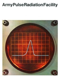
Army Pulse Radiation Facility
[Illustration]
Contents
Page No.
The Concept 3
The Facility 5
The Reactor 7
Exposure Locations and Performance Levels 11
APRF User Support Facilities 17
Instructions to Potential Users 20
Table I.
APRFR Core Design Data 8
Table II.
Typical APRFR Performance Levels 8
Table III.
APRFR Fluence and Flux Data 13
Table IV.
Nominal APRFR Leakage and U235 Fission Spectra 13
Table V.
Fluence-to-Dose Conversion Factors for APRFR Leakage Neutrons 14
Table VI.
Kerma and Kerma Rate in Tissue for APRFR Exposure Conditions 14
Table VII.
Kerma and Kerma Rate in Silicon for APRFR Exposure Conditions 15
Table VIII.
Neutron-to-Gamma Dose Ratios 15
Table IX.
APRF User Support Equipment 18
Army Pulse Radiation Facility
_U.S. Army Ballistic Research Laboratories_
AMXRD-BTD
_Aberdeen Proving Ground, Maryland 21005_
[Illustration: Army Pulse Radiation Facility Location Map]
[Illustration]
The Concept
The Army Pulse Radiation Facility (APRF) is designed to meet an
Army need for a facility located near the Eastern Seaboard capable
of providing large fast neutron and gamma radiation doses within
microseconds. This fast pulse radiation capability is necessary for
the determination of transient responses of materiel in nuclear
environments.
The APRF increases Army capability by providing improved simulation of
radiative effects of a nuclear burst for studies of Army interest, and
provides a facility for testing Army materiel. Because of its location,
the APRF economically and efficiently serves the heavy concentration of
Army agencies and contractors located along the Eastern Seaboard.
The design of the APRF is a direct outgrowth of projected user
requirements. Thus the reactor can be used both for high dose
irradiations of small objects, as a point source for radiation detector
studies, and irradiation of bulk objects. The former requirement led
to the incorporation of a 1½-inch OD “glory hole” running through
the center of the core, and providing a fast neutron fluence of
about 9 × 10¹⁴ neutrons per square centimeter per pulse. The latter
two requirements have resulted in the design of a large volume,
low-radiation backscatter Reactor Building. Provision is made for
moving the reactor both within the Reactor Building and to an outdoor
test site at heights variable up to 44 feet above ground by means of a
mechanical device called the reactor transporter. The reactor is also
capable of intermittent steady state operation in the kilowatt range
for classes of experiments requiring this mode of operation.
[Illustration]
[Illustration]
[Illustration]
The Facility
The APRF is located on the military reservation of Aberdeen Proving
Ground (APG), in southeastern Harford County, Maryland. The Reactor
Building is at the center of the facility.
This building is a windowless, circular structure with aluminum siding.
Inside, the building is 100 feet in diameter and 65 feet high. There
is a roll-up door in the south wall for the passage of the reactor
transporter to the outdoor test site and another in the west wall for
the access of vehicles to the building. A shielded stairway and maze
provides access from the underground Control Building. This concrete
structure provides radiological shielding for the personnel and
controls associated with the operation of the reactor and the conduct
of experiments.
The area within a ~450-yard radius of the Reactor Building constitutes
the APRF high-radiation area defined by a 10-foot anti-personnel fence.
This high-radiation area is in turn surrounded by a nearly concentric
restricted area defined at its outer boundary by a barbed wire warning
fence at a radius of ~1500 yards from the Reactor Building.
The Laboratory Building, located at the periphery of the restricted
area, houses the administrative and support personnel for the APRF.
Access to APRF is controlled at this point.
[Illustration: APRF Reactor Core Assembly]
[Illustration]
The Reactor
The reactor, (APRFR), is designed for both self-limited,
super-prompt-critical pulse operation and steady state operation. The
maximum available pulse has a yield of ~2.1 × 10¹⁷ fissions, while
steady state operation is limited to about 10 kilowatts by the reactor
core cooling system and activation of the core.
[Illustration: High Yield Prompt Pulse Shape]
The APRFR is an advanced version of the Health Physics Research
Reactor (HPRR) at Oak Ridge National Laboratory (ORNL), which has
been operating since 1962. ORNL has played a key role in the design
and testing of the APRFR. In pulse operation, the power level may
rise on periods as short as 10 microseconds. Electro-mechanical scram
systems are too slow to terminate such an excursion. Shutdown results
from increased neutron leakage due to fuel expansion, resulting in
a large prompt negative temperature coefficient of reactivity. This
self-limiting feature depends almost entirely on the thermal expansion
of the fuel alloy, and thus it is regarded as completely reliable and
safe.
Following a pulse, additional reactor shutdown capability is provided
by a safety block which, when ejected from the core, reduces the
reactivity to about 20 dollars below delayed-critical. At lower yield
pulses, below about 6 × 10¹⁶ fissions, the safety block is ejected by
the electro-mechanical scram system in about 0.1 seconds after a pulse.
At higher yield pulses, the safety block is ejected in much shorter
times due to thermo-mechanical shock forces which cause the safety
block to bounce out. The large shutdown margin provided by the safety
block is also the primary design device for preventing accidental
criticalities during periods of reactor shutdown.
The APRFR core is an unmoderated cylindrical assembly containing about
125 kilograms of an alloy of uranium 235 containing 10% molybdenum. The
actual core mass varies with the experiment. The core is cylindrical
and consists of two concentric annuli: a fixed outer shell of stacked
fuel discs bolted together with nine fuel bolts and Inconel nuts and
a movable inner safety block, also of fuel alloy. The 1½-inch OD
“glory hole” runs vertically through the center of the safety block.
Key reactor data is summarized in Tables I and II. The APRFR has been
operated during tests at ORNL at more than twice its design yield.
Table I.
APRFR Core Design Data
Core Diameter 8.90 inches
Core Height[1] 8.0 inches
Fuel Alloy 90 wt % uranium -
10 wt % molybdenum
Uranium-235 Enrichment 93.14%
Total Fuel Mass[2] 125
Safety Block Mass 15.7 kg
Safety Block Height 8.06 inches
Safety Block Diameter 4.00 inches
Glory Hole Diameter 1.50 inches
Number of Control Rods Three
Core Cooling Forced Air
Number of Core Bolts Nine
Safety Block Reactivity Worth ~$20
Pulse Rod Reactivity Worth ~$1.15
Core Environment During Pulse Dry Nitrogen
Core Cooling Forced Air
[1] This value varies with experimental environment of core.
[2] This value varies with experimental environment of core.
Table II.
Typical APRFR Performance Levels
PULSE MODE
Routine Yield 1.5 × 10¹⁷ fissions/pulse
Reactivity Insertion $1.10
Pulse Half-Width 48 μsec
Initial Prompt Period 18 μsec
Maximum Fuel Temperature Rise 400°C
Temperature Coefficient -0.3 cents/°C
Maximum Available Yield ~2.1 × 10¹⁷ fissions/pulse
STEADY STATE MODE
Continuous Operation ~1 kw
Intermittent Operation ~10 kw
Steady state power levels are limited by effectiveness of core cooling
system and core activation.
[Illustration]
[Illustration: APRF Floor Plan]
Exposure Locations and Performance Levels
The highest fluence and dose rates are available in the 1½-inch glory
hole. Since the reactor is supported from above by the transporter, the
areas around and below the core are also available for experiments.
The core can be positioned by remote control anywhere within the range
of travel of the transporter. Vertical travel is limited to about 44
feet above the Reactor Building floor level. Horizontal travel is
limited by the range of the rails on which the transporter travels. Six
pairs of rails extend radially from a turntable in the center of the
Reactor Building. These rails terminate within the Reactor Building,
except for one pair which extends 90 feet outside the building to an
outdoor test site. Each pair of rails defines one experimental location
where semi-permanent equipment and shielding can be set up without
tying up the entire reactor operation.
Fluence and flux data for three typical exposure locations are given in
Table III. In the absence of reflecting material beyond 1 meter from
core center (position P3), these values fall off essentially as
1
——
R²
where R is the distance to core center. Other performance data are
summarized in Tables IV through VIII.
[Illustration]
[Illustration]
[Illustration]
[Illustration]
Table III.
APRFR Fluence and Flux Data
-------------------------------------------------------------------
Routine Pulse Yield Maximum Pulse Yield
1.5 × 10¹⁷ Fissions 2.1 × 10¹⁷ Fissions
-------------------------------------------------------------------
Fluence, n/cm²
P1[3] 6.7 × 10¹⁴ 9.3 × 10¹⁴
P2 2.0 × 10¹⁴ 2.8 × 10¹⁴
P3 1.7 × 10¹² 2.4 × 10¹²
Flux Density, n/cm²/sec
P1 1.4 × 10¹⁹ 2.0 × 10¹⁹
P2 4.3 × 10¹⁸ 6.0 × 10¹⁸
P3 3.7 × 10¹⁶ 5.2 × 10¹⁶
[3] P1: Center of Glory Hole; P2: Core Surface (11.3 cm from Core
Center); P3: 1 meter from Core Center.
Table IV.
Nominal APRFR Leakage and U235 Fission Spectra[4]
--------------------------------------------------------
Energy Average APRFR U235 Fission
Group Energy Energy Spectrum Spectrum
Number Range Eₙ Fraction Fraction
n (Mev) (Mev) XₙΔEₙ XₙΔEₙ
--------------------------------------------------------
1 3.0-∞ 4.41 0.133 0.204
2 1.4-3.0 2.10 0.251 0.344
3 0.9-1.4 1.14 0.164 0.168
4 0.4-0.9 0.65 0.262 0.180
5 0.1-0.4 0.26 0.168 0.090
6 0-0.1 0.059 0.022 0.014
-------------------
SUM 1.000 1.000
-------------------
Mean Energy (Mev) ~1.55 ~1.8
[4] These values are approximate and meant for qualitative comparison
only.
Table V.
Fluence-to-Dose Conversion Factors for APRFR Leakage Neutrons
--------------------------------------------------------------------
Material Quantity Conversion Factor
--------------------------------------------------------------------
Tissue Kerma 2.4 × 10⁻⁷ erg/gram
-----------
neutron/cm²
Tissue Maximum Absorbed Dose For 3.5 × 10⁻⁹ rad
-----------
neutron/cm²
Normally Incident Neutrons
Silicon Elastic Recoil Kerma 2.7 × 10⁻⁹ erg/gram
(~Permanent Effect) -----------
neutron/cm²
Silicon Ionization Kerma 2.9 × 10⁻⁹ erg/gram
(~Transient Effects) -----------
neutron/cm²
Silicon (Total) Kerma 5.6 × 10⁻⁹ erg/gram
-----------
neutron/cm²
--------------------------------------------------------------------
Table VI.
Kerma and Kerma Rate in Tissue for APRFR Exposure Conditions
--------------------------------------------------------------------
Routine Pulse Yield Maximum Pulse Yield
1.5 × 10¹⁷ Fissions 2.1 × 10¹⁷ Fissions
--------------------------------------------------------------------
Kerma in Tissue
(ergs/gm)
P1[5] 1.6 × 10⁸ 2.2 × 10⁸
P2 4.9 × 10⁷ 6.8 × 10⁷
P3 4.1 × 10⁵ 5.7 × 10⁵
Kerma Rate in Tissue
(ergs/gm/sec)
P1 3.5 × 10¹² 4.7 × 10¹²
P2 1.1 × 10¹² 1.5 × 10¹²
P3 8.8 × 10⁹ 1.2 × 10¹⁰
[5] P1: Center of Glory Hole; P2: Core Surface; P3: 1 Meter from Core
Center.
[Illustration]
[Illustration]
[Illustration]
[Illustration]
Table VII.
Kerma and Kerma Rate in Silicon for APRFR Exposure Conditions
--------------------------------------------------------------------
Routine Pulse Yield Maximum Pulse Yield
1.5 × 10¹⁷ Fissions 2.1 × 10¹⁷ Fissions
--------------------------------------------------------------------
Total Kerma in Silicon,
ergs/gm[6]
P1[7] 2.7 × 10⁶ 5.2 × 10⁶
P2 1.1 × 10⁶ 1.6 × 10⁶
P3 9.5 × 10³ 13.3 × 10³
Total Kerma Rate in
Silicon, (ergs/gm/sec)
P1 5.8 × 10¹⁰ 11.0 × 10¹⁰
P2 2.4 × 10¹⁰ 3.5 × 10¹⁰
P3 2.0 × 10⁸ 2.9 × 10⁸
[6] Ionization and elastic recoil processes contribute roughly equal
amounts to the total kerma.
[7] P1: Center of Glory Hole; P2: Core Surface; P3: 1 Meter from Core
Center.
Table VIII.
Neutron-to-Gamma Dose Ratios[8]
-----------------------------------------------------------------
neutron rads tissue n/cm²/sec
------------------- -----------------
gamma rads tissue gamma rads tissue
-----------------------------------------------------------------
Core Center (P1) 10 2.7 × 10⁹
Core Surface (P2) 10 2.7 × 10⁹
1 Meter from Core Center (P3) 9 3.3 × 10⁹
10 Meters from Core Center 7 2.5 × 10⁷
[8] Representative data. Actual values influenced by core operating
history.
[Illustration: Cross Section of Reactor Building]
APRF User Support Facilities
APRF is designed and staffed to assist its users in all key areas
relating to reactor utilization.
=Physical Space= Several areas in the underground Control Building
are available to experimenters. These include the trailer tunnel with
room for two full-sized trailers, the data acquisition room, and the
instrument shop. All of these areas are provided with conduits so that
cables can be run directly to them from the Reactor Building. In the
trailer tunnel the minimum cable length required to run to the core
surface is about 30 feet.
The exposure areas in the Reactor Building and the outdoor test site
are equipped with conduits for communication and instrumentation cables.
Available areas in the Laboratory Building include a high-bay set
up area, a machine shop, laboratory space, fume hood with remote
manipulator, photography laboratory, and offices.
=Data Acquisition and Processing= The basic element here is the
APRF Data Acquisition System described in Table IX. Various other
instrumentation is available as summarized in Table IX. Data processing
is available at the ARDC computer center and with on-line equipment at
APRF.
=Dosimetry= Routine dosimetry is performed by APRF personnel.
Methods available include fluence and spectrum measurements using
foil techniques, glass rod microdosimetry, thermoluminescence, and
diverse active dosimeters. Foils are analyzed using the APRF Automatic
Dosimetry System and data are available within a short time following
exposure.
Measurements are supplemented by analytical methods including one
and two dimensional transport theory, Monte Carlo, and special foil
analysis codes.
=Staff= The APRF staff is available to guide, plan and set up
experiments at the reactor, perform dosimetry, and assist in data
acquisition. APRF participation is determined on a case-by-case basis.
=Health Physics= Health physics survey, monitoring, decontamination
and related services are available in conjunction with the BRL Health
Physics Division.
Table IX.
APRF User Support Equipment
--------------------------------------------------------------------
=Transient Data Recording System=
--------------------------------------------------------------------
TAPE RECORDERS: _Three each—14 track Honeywell Model 7600_
FREQUENCY: _DC to 80 kHz FM, 400 Hz to 700 kHz Direct_
SIGNAL _Universal Strain gauge and thermocouple with_
CONDITIONING: _100 KC DC amplifiers_
TIME CODE: _IRIG A, 1 millisecond resolution_
PATCH PANELS: _Coaxial and triaxial connectors for all inputs_
_and outputs, insulated shields._
AUTO CALIBRATION: _50 channel, 3 step_
CHANNEL ID: _Automatic ID in binary code_
PLAYBACK: _12” oscillograph_
--------------------------------------------------------------------
=Dosimetry=
--------------------------------------------------------------------
Basic Foil Calibration System
5000 Curie Co-60 source
Automated Sulfur, Fission Foil and Gamma Well Counting System,
100 Samples each per cycle
Eight channel active dosimeter system with digital read out and
computer analysis of neutron fluence and energy
Toshiba Glass Rod and Harshaw TLD Gamma System
--------------------------------------------------------------------
=Computer=
--------------------------------------------------------------------
16 bit/16K memory with foreground/background operation. Automatic
acquisition and reduction of foil counting data on-line. On-line
monitoring of reactor power pulse with analysis of peak, half-width
and yield. On-line monitoring of active dosimeters with data
reduction. Real time/Fortran IV.
--------------------------------------------------------------------
=General Equipment=
--------------------------------------------------------------------
3300 Nuclear Data Multiparameter Analyzer, 4096 channel with
magnetic tape; RIDL 400 Channel Pulse Height Analyzer.
Oscilloscopes, cameras, electronic calibration equipment.
Hood areas with manipulators, photographic laboratory, radiation
monitoring equipment and services, machine shop.
--------------------------------------------------------------------
[Illustration]
[Illustration]
[Illustration]
[Illustration]
[Illustration]
Instructions To Potential Users
It is imperative to realize that there are stringent safety
requirements connected with the use of the APRFR. All experiments will
follow a written test plan approved at APRF. In order to perform an
experiment with maximum usefulness and efficiency, it is essential
that APRF be contacted during the early planning stages of a potential
experiment. Failure to do this may result in erroneous experiment
planning as regards safety and use of exposure space resulting in
schedule delays, and possibly cancellation or drastic revision of the
experiment.
_For further information contact_:
Commanding Officer
U.S. Army Ballistic Research Laboratories
ATTN: AMXRD-BTD, Facility Coordinator
Aberdeen Proving Ground, Maryland 21005
*** END OF THE PROJECT GUTENBERG EBOOK 68120 ***
Army Pulse Radiation Facility
Subjects:
Download Formats:
Excerpt
Underscores “_” before and after a word or phrase indicate _italics_
in the original text.
Equal signs “=” before and after a word or phrase indicate =bold=
in the original text.
Illustrations have been moved so they do not break up paragraphs.
Typographical and punctuation errors have been silently corrected.
The Concept 3
The Facility 5
The Reactor...
Read the Full Text
— End of Army Pulse Radiation Facility —
Book Information
- Title
- Army Pulse Radiation Facility
- Author(s)
- U.S. Army Ballistic Research Laboratory
- Language
- English
- Type
- Text
- Release Date
- May 19, 2022
- Word Count
- 2,325 words
- Library of Congress Classification
- TK
- Bookshelves
- Browsing: Computers & Technology, Browsing: Engineering & Construction
- Rights
- Public domain in the USA.